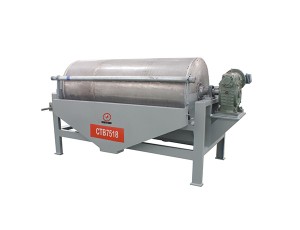
Flotation Machine or Flotation Cell


Flotation Machine or Flotation Cell
Working Principal
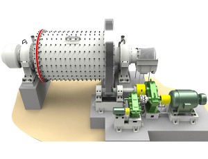
The impellers are driven through V belt transmission, which brings centrifugal effect to form the negative pressure. On the one hand, the flotation machine inhales sufficient air to mix with ore slurry; on the other hand, it stirs ore slurry and mix with medication to form the mineralized froth. To adjust the height of flashboard to control the liquid level and make the useful froth scraped by loam board. Each chute can inhale gas, sink magma, separate. No assisting equipments are required, and it must be levelly installed. It is easy to change the flow chart. The cycling way of magma is very reasonable. It can reduce the impurities to a great extent. There is automatic equipment on the magma surface, easy to adjust. The impeller also owns the upper and lower retroversion blade. The upper one makes the magma cycle upward, while the lower one makes the magma cycle downward.
Technical Data
|
Model |
Cell Volume |
Impeller |
Impeller speed |
Capacity |
Major |
Scraper motor power(kW) |
Weight |
|
SF0.37 |
0.37 |
300 |
442 |
0.2-0.4 |
1.5 |
1.1 |
0.4 |
|
SF0.7 |
0.7 |
350 |
400 |
0.3-1 |
3 |
1.1 |
0.9 |
|
SF1.2 |
1.2 |
450 |
312 |
0.6-1.2 |
5.5 |
1.1 |
1.4 |
|
SF2.8 |
2.8 |
550 |
268 |
1.5-3.5 |
11 |
1.1 |
2.2 |
|
SF4 |
4 |
650 |
235 |
15 |
15 |
1.5 |
2.6 |
|
SF8 |
8 |
760 |
191 |
30 |
30 |
1.5 |
4.3 |
|
SF16 |
16 |
850 |
190 |
45 |
45 |
1.5 |
7.4 |
|
Model |
Cell Volume |
Impeller |
Impeller speed |
Capacity |
Major |
Scraper motor power(kW) |
Weight |
|
BF2.8 |
2.8 |
550 |
278 |
0.9-1.1 |
1.4-3 |
11 |
2.1 |
|
BF4 |
4 |
650 |
235 |
0.9-1.1 |
2.4-4 |
15 |
2.6 |
|
BF6 |
6 |
700 |
205 |
0.9-1.1 |
3-6 |
18.5 |
3.3 |
|
BF8 |
8 |
760 |
188 |
0.9-1.1 |
4-8 |
22 |
4.1 |
|
BF10 |
10 |
760 |
188 |
0.9-1.1 |
5-10 |
22 |
4.5 |
|
BF16 |
16 |
850 |
195 |
0.9-1.1 |
8-16 |
37 |
8.3 |
|
BF20 |
20 |
850 |
195 |
0.9-1.1 |
10-20 |
45 |
8.7 |
|
BF24 |
24 |
920 |
181 |
0.9-1.1 |
12-24 |
45 |
9 |
|
Model |
Cell Volume |
Impeller diameter |
Impeller |
Blower pressure |
Max.air inflow volume |
Capacity |
Major motor power |
Scraper motor power |
Weight |
|
KYF1 |
1 |
340 |
281 |
≥12.6 |
2 |
0. 2-1 |
4 |
1. 1 |
0. 8 |
|
KY-2 |
2 |
410 |
247 |
≥14.7 |
2 |
0. 4-2 |
5. 5 |
1. 1 |
1. 5 |
|
KYF3 |
3 |
480 |
219 |
≥19.8 |
2 |
0. 6-3 |
7. 5 |
1. 5 |
1. 9 |
|
KYF4 |
4 |
550 |
200 |
≥19.8 |
2 |
1. 2-4 |
11 |
1. 5 |
2. 2 |
|
KYF8 |
8 |
630 |
175 |
≥21.6 |
2 |
3. 0-8 |
15 |
1. 5 |
4. 2 |
|
KYF16 |
16 |
740 |
160 |
≥25.5 |
2 |
4. 0-16 |
30 |
1. 5 |
6 |
|
KYF24 |
24 |
800 |
150 |
≥30.4 |
2 |
4. 0-24 |
30 |
1. 5 |
7. 5 |
|
KYF38 |
38 |
880 |
138 |
≥34.3 |
2 |
10-38 |
37 |
1. 5 |
10. 3 |
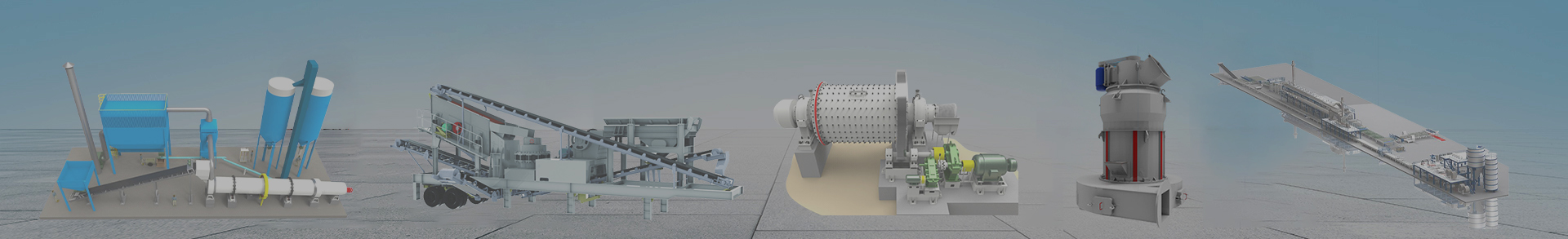
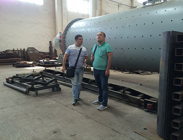
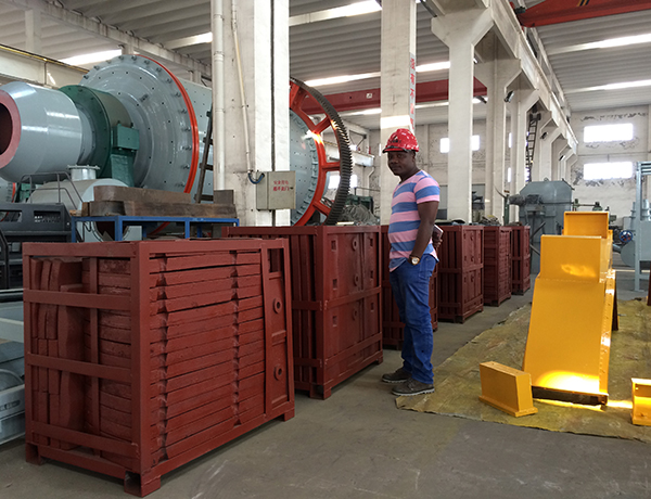
Customer Visiting
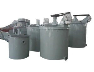
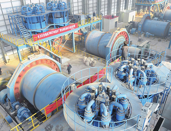
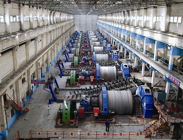
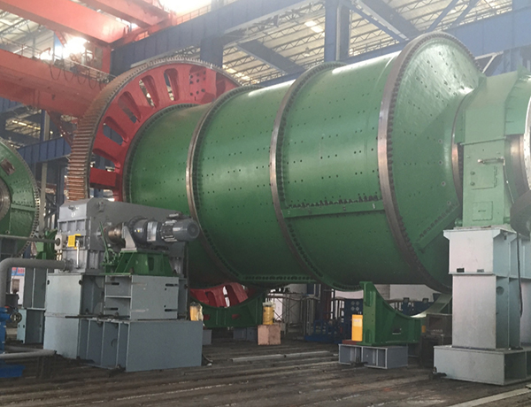
Working Sites’ Pics
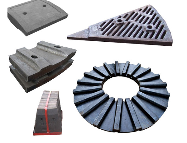
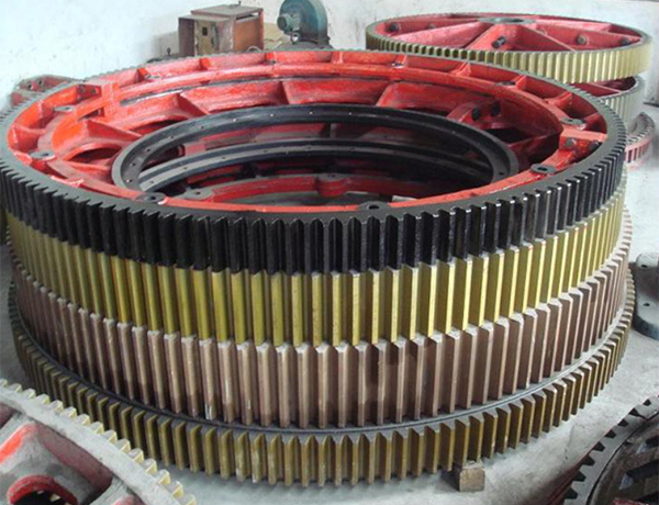
Spare Parts